Ever wondered how your car’s engine knows exactly how much power to deliver, whether you’re gently cruising down the highway or demanding quick acceleration? The answer lies in a sophisticated network of sensors that act as the engine’s eyes and ears, constantly feeding vital information to the brain – the Engine Control Unit (ECU). Among these many crucial components, a handful stand out as the primary architects of your vehicle’s power output. Let’s dive into five key car sensors that play a pivotal role in managing and optimizing your engine’s performance.
1. The Breathing Monitor: Mass Airflow (MAF) Sensor
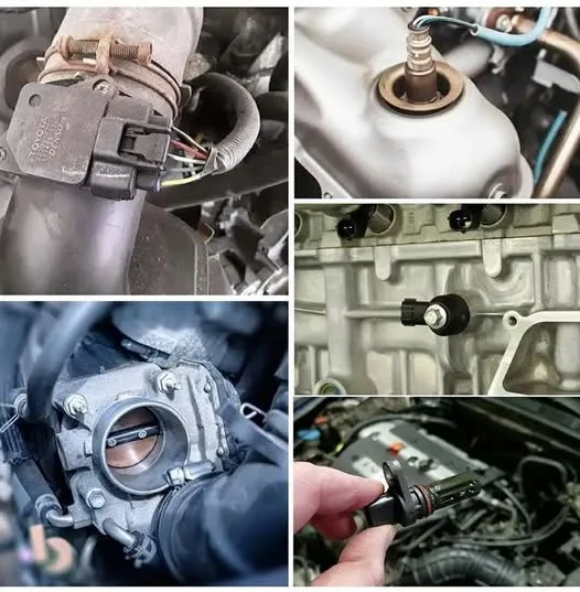
Imagine your engine as an athlete. To perform at its peak, it needs the right amount of oxygen. That’s where the Mass Airflow (MAF) sensor comes in. Located in the air intake system, typically after the air filter, this sensor meticulously measures the mass of air entering the engine.
Think of it like this: the more air the engine takes in, the more fuel it can efficiently burn, leading to increased power. The MAF sensor sends a precise electrical signal to the ECU, indicating the exact amount of air ingested. Armed with this information, the ECU can calculate the precise amount of fuel to inject into the cylinders. Too little fuel and the engine will run lean, potentially causing damage and reduced power. Too much fuel and it will run rich, leading to wasted fuel and increased emissions. The MAF sensor ensures that perfect balance for optimal power delivery and efficiency.
2. The Pedal Translator: Throttle Position Sensor (TPS)
You press the accelerator pedal, and the car responds with more speed. But how does the engine know how much power you’re asking for? Enter the Throttle Position Sensor (TPS). This sensor is typically located on the throttle body, the part that controls the airflow into the engine’s intake manifold.
The TPS directly monitors the angle or position of the throttle plate, which is connected to your accelerator pedal via a cable or electronic linkage. As you press down on the pedal, the throttle plate opens wider, allowing more air into the engine. The TPS sends a voltage signal to the ECU that is directly proportional to the throttle plate’s opening. The ECU interprets this signal to understand your power demand. A slight pedal press translates to a small throttle opening and a modest power increase, while a full stomp on the accelerator signals the ECU to unleash the engine’s full potential.
3. The Exhaust Analyst: Oxygen (O2) Sensor
Once the combustion process is complete, the exhaust gases carry valuable information about its efficiency. The Oxygen (O2) sensor, strategically placed in the exhaust system (usually before and after the catalytic converter), acts as a chemical analyst, measuring the amount of oxygen present in these gases.
The ECU uses the data from the O2 sensor to fine-tune the air-fuel mixture in real-time. If the exhaust contains too much oxygen, it indicates a lean burn (too much air, not enough fuel), and the ECU will command the fuel injectors to deliver more fuel. Conversely, if there’s too little oxygen, it signifies a rich burn (too much fuel, not enough air), and the ECU will reduce fuel injection. Maintaining the ideal air-fuel ratio (around 14.7:1 for gasoline engines, known as stoichiometry) is crucial for optimal combustion, maximum power, and minimizing harmful emissions. A healthy O2 sensor is vital for a responsive and efficient engine.
4. The Knock Detector: Knock Sensor
Engine knock, also known as pinging or detonation, is an abnormal and potentially damaging combustion event where the fuel-air mixture ignites prematurely and uncontrollably in the cylinder. This can lead to a characteristic knocking or pinging sound and, if left unchecked, can cause serious engine damage.
The knock sensor, typically mounted directly on the engine block, is designed to “listen” for these specific vibrations caused by knock. When it detects these vibrations, it sends a signal to the ECU. In response, the ECU will immediately retard (delay) the ignition timing. Retarding the timing gives the combustion process more time to occur in a controlled manner, preventing the damaging effects of knock and safeguarding the engine’s integrity. By proactively preventing knock, the knock sensor allows the engine to operate with more aggressive ignition timing under normal conditions, which translates to improved power and efficiency.
5. The Valve Timing Guardian: Camshaft Position Sensor
The camshaft is a critical component that controls the opening and closing of the engine’s intake and exhaust valves. Precise timing of these valve events is crucial for proper engine operation, including efficient intake of air and fuel and effective expulsion of exhaust gases.
The Camshaft Position Sensor monitors the rotational position of the camshaft. This information is vital for the ECU to determine the exact position of the pistons and, consequently, to precisely time the firing of the spark plugs and the injection of fuel into the correct cylinder at the optimal moment. Without accurate camshaft position data, the engine wouldn’t know when to initiate these critical events, leading to poor performance, misfires, and even a failure to start. By ensuring accurate synchronization of the engine’s mechanical and electrical systems, the camshaft position sensor plays a fundamental role in delivering smooth and consistent power.
In Conclusion:
These five sensors – the MAF, TPS, O2 sensor, knock sensor, and camshaft position sensor – are integral to your car’s ability to generate and manage power effectively. They work tirelessly, constantly providing the ECU with the real-time data it needs to makeSplit-ring induction motors are a type of electric motor used in a variety of applications, from small household appliances to large industrial machinery. They are known for their reliability, efficiency, and ability to provide high starting torque. Let’s explore some of the key characteristics and applications of these motors.
Key Characteristics:
- Rotor Construction: The defining feature of a split-ring induction motor is its rotor. The rotor consists of a laminated cylindrical core with slots that house the rotor winding. The ends of these windings are connected to copper or brass end rings. Crucially, these end rings are segmented, forming “split rings.”
- Squirrel Cage Equivalent: Functionally, the split-ring rotor operates similarly to the squirrel cage rotor found in standard induction motors. The stator’s rotating magnetic field induces currents in the rotor bars (the windings connected to the end rings). These induced currents create their own magnetic field, which interacts with the stator field to produce torque and rotation.
- Simplified Construction: Compared to other types of induction motors with wound rotors and slip rings, split-ring motors have a simpler and more robust rotor design. This contributes to their reliability and lower maintenance requirements.
- Self-Starting: Like squirrel cage induction motors, split-ring induction motors are self-starting. When power is applied to the stator windings, the rotating magnetic field automatically induces currents in the rotor, generating the necessary starting torque.
- Relatively Constant Speed: Under a constant load, split-ring induction motors tend to operate at a relatively constant speed close to the synchronous speed determined by the frequency of the power supply and the number of magnetic poles in the stator.
- Efficiency: These motors can achieve good efficiency in their operating range, making them a practical choice for many applications.
Applications:
Split-ring induction motors are widely used in a diverse range of applications due to their advantageous characteristics:
- Household Appliances: They are commonly found in appliances like washing machines, refrigerators, fans, vacuum cleaners, and kitchen mixers. Their reliability and relatively quiet operation make them suitable for these domestic uses.
- Industrial Machinery: Smaller to medium-sized industrial equipment, such as pumps, compressors, conveyors, and machine tools, often utilize split-ring induction motors for their robust performance and ease of control (primarily through direct-on-line starting or simple starters).
- HVAC Systems: Fans and blowers in heating, ventilation, and air conditioning (HVAC) systems frequently employ these motors for their efficiency and ability to provide the necessary airflow.
- Power Tools: Some power tools, particularly those requiring consistent speed under load, utilize split-ring induction motors.
- Automation and Robotics: In certain automation and robotic applications where precise speed control isn’t the primary requirement, these motors can provide reliable and cost-effective motion.
Advantages:
- Simple and Robust Construction: Fewer moving parts in the rotor lead to higher reliability and lower maintenance.
- Self-Starting Capability: No need for external starting mechanisms in most applications.
- Relatively High Efficiency: Efficient operation within their design parameters.
- Lower Manufacturing Cost: Simpler rotor design can contribute to lower production costs compared to wound rotor motors.
Limitations:
- Limited Speed Control: Speed control is generally achieved through changing the frequency of the power supply or using more complex electronic drives. Inherently, they have limited adjustable speed capabilities compared to wound rotor motors with external rotor resistance control.
- Lower Starting Torque Compared to Wound Rotor Motors: While they provide sufficient starting torque for many applications, they generally don’t offer the very high starting torque achievable with wound rotor induction motors and external rotor resistance.
In conclusion, split-ring induction motors represent a workhorse in the world of electric motors. Their blend of simple yet effective design, reliability, efficiency, and self-starting capability makes them an ideal choice for a vast array of applications, continuing to power many aspects of our daily lives and industrial processes.